Many Innovations.
Much could be written regarding the tasteful schemes of decoration which distinguish the various apartments, and in the course of this article we shall touch upon the nature of the equipment. In the first place, however, we propose to deal with the machinery. Particularly with regard to the auxiliary plant, certain innovations are to be found and a remarkable feature of the entire installation, not only as regards the choice of propelling and auxiliary machinery. but the passenger accommodation in addition, is: that it largely represents the results of the enterprise of one individual, namely, Mr. Woods, who is the general manager of the Nelson Line.
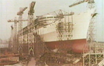
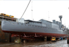
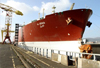
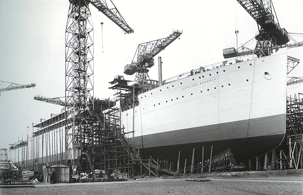
The Highland Monarch was built and engined by Harland and Wolff at Belfast, and there are four sister ships to follow, one being already launched. This is the Highland Chieftain; the third and fourth vessels are to be named Highland Brigade and Highland Hope, a decision as to the name of the fifth liner being under consideration (She was subsequently named Highland Princess). It is expected that all the vessels will be in commission by July, 1929, and they will maintain a fortnightly service between the United Kingdom, Brazil and the Argentine via Spain and Portugal. The carriage of refrigerated produce, apart from passengers and general cargo, forms an important feature of the trade in question. In the following table are given the leading particulars of the five ships. So far as the hulls, propelling engines and most of the auxiliary plant ale concerned the five ships are alike, the main difference being with regard to the refrigerating machines.
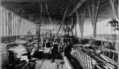
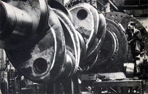
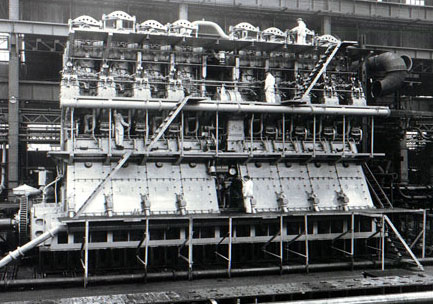
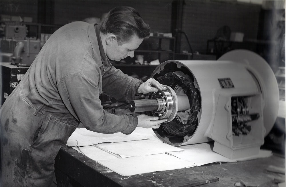
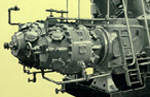
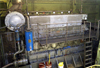
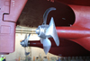
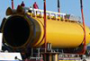
Descriptions have appeared in this journal relative to the double-acting four-stroke Burmeister and Wain design of marine Diesel engine on various occasions; it will be sufficient, therefore, if we recapitulate a few of the main points, for this class of machinery has been virtually resolved into a standard type built by different manufacturers, but embodying no variations of special note. We may, however, draw attention to the reproductions from photographs of the machinery which were specially taken by us when the vessel was in London.
It will be noted from the table that each of the two 4,000 b.h.p. Harland and Wolff B&W engines in the Highland Monarch has eight cylinders with a diameter of 680 mm., the stroke being 1,600 mm., and the speed 100 r.p.m.; the motors are similar to the units installed in the passenger liners Accra and Apapa, except as regards the number of cylinders and the length of the piston stroke,
Fuel-valve Lift Control.
With the Nelson liner’s engines there is a fuel -valve variation lift mechanism both for the top and bottom valves, which are operated by push-rods having rollers actuated by cams on a single camshaft driven by means of a chain. A handwheel located at the control station alters the lift of the lower valves, whereas there are two wheels, operated from one of the upper platforms, for the valves in the top covers. These covers are of the usual square type, each carrying four bolts or tie-rods which extend to the bedplate. The mounting of each cylinder is entirely separate.
Above and below the camshaft, which is moved fore and aft by a servo motor when reversing the engine, are two cranked layshafts which clear the rollers from the cams. Inlet, exhaust, fuel, starting air and relief valves are fitted at each end; the top valves and carried in the cover in the usual way, whereas the lower valves are mounted in a casting attached to the bottom cover, which carries the stuffing box and gland for the piston rod. Each main engine drives - two three-stage blast injection air compressors from an extension of the crankshaft at the forward end. The control station is in the usual position below, and .does not differ materially from that of the single-acting engine.
An Exhaust Gas Boiler.
The exhaust gases pass to a Clarkson thimble-tube boiler located at the top of the engine room forward. Suitable flap valves are provided in order to direct the exhaust to the silencers without passing through the boiler, if required. At the time we inspected this part of the installation one engine was utilized on the boiler and the steam pressure \vas 60 lb. per sq. in. For use in port a Clyde oil-fuel system is installed, two burners being fitted, whilst steam nozzles are also provided, the steam acting as an atomizing agent in case of failure of the current supplying the blower motor. The boiler is designed to generate 4,800 lb. of steam hourly, on 70 per cent. of~ the total quantity of exhaust gas available, the heating surface being 600 sq. ft. The diameter is 6 ft. and the height 12 ft. 6 ins., while the combustion chamber 15 5 ft. in diameter and 6 ft. 4 ins, in height.
Thrust Indicating Gear and Oily Vapour Extractors.
The main thrust blocks are of the Michell single-collar type, and each is fitted with a pump and gauge for taking a reading of the actual thrust by means of hydraulic mechanism. Adjacent are the electric turning motors, each being a 15 h.p. machine running at 700 r.p.m. Among other accessories to the main engines are the extractors provided for drawing the oily vapour from the crankcase. These extractors, however, are not normally in use and are chiefly intended for employment when the vessel is in tropical waters For ascertaining the exhaust temperatures of each top and bottom combustion chamber on both main engines, Siemens pyrometers are fitted, instruments of the same type, but naturally less elaborate, being used in connection with the auxiliary generating sets, of which mention will be made later. With regard to the engine-room telegraphs, the bells continue to ring after a change of orders from the bridge until the engineer replies. Ahead and astern revolution indicators are fitted on the bridge, together with speed indicators, and there is a comprehensive telephone system installed. All of this equipment is of Messrs. Siemens’ manufacture, and it may be noted that a special telephone box is installed at the after-end between the main engines.
On the port side aft is a battery of centrifugal separators, comprising five Sharples machines. Three of the separators are of the totally-enclosed design and are provided for treating the fuel, two being of the open type and intended to deal with the lubricating oil. A similar arrangement will be adopted in the remaining four ships. The main engine pistons are cooled by means of lubricating oil derived from a system common to the bearings. There are four vertical four-stage Allen pumps at the after-end of the engine-room, each having a capacity of 100 tons hourly and driven by a 50 b.h.p. motor running at 1,250-1,500 r.p.m. The pumps are fitted with Zwicky filters, and a flexible coupling connects the pump and motor shafts. The oil is stored in the double bottoms, and is pumped through large Auto-Klean strainers to the coolers, where the oil is cooled before passing to the engines. Two strainers are provided for each engine, the capacity being 180 tons of oil an hour when the machinery is operating at full output. The strainer cartridges are, non-collapsible circular discs with cleaners between; the strainer plates are 0.008" apart and the loss of pressure across the strainers during the full power trials was 4.5 lb. to 5 lb. per sq. in. Each pair of strainers is coupled by a common main pipe 7.5". in diameter, inlet and outlet stop valves being provided. We understand that apart from turning the cleaner handles once a watch the strainers will require no attention during a round voyage.
Pumping Machinery.
With a propelling installation of the size and. type installed in the Highland Monarch it will be realized that the pumping machinery, which is electrically operated throughout, is an important part of the equipment. The main lubricating-oil pumps, driven by motors totaling 200 h.p., have already received reference. On the port side of the engine-room there is a Drysdale 5-in, upright pump for sanitary purposes, the capacity being 100 tons an hour. The drive is furnished by a 29 b.h.p. motor running at 1,650 r.p.m. A similar unit is installed for fire service. The fresh-water pump is of the twin plunger type driven by a 4.5 h.p. motor running at 800 r.p.m. There is a Centrex 0-in, pump for bilge duty driven by a 13 b.h.p. Laurence Scott motor running at 1,300 r.p.m., the capacity being 120 tons per hour. The ballast pump, which has a capacity of 250 tons per hour, is also of the Centrex type. On the port side forward there is an auxiliary fresh-water circulating pump driven by a 6.5 h.p. motor running at 1,400 r.p.m. For cooling the main engine circulating water two large coolers are arranged on the port and starboard sides of the engine-room aft. These are fitted with separate pumps for the purpose of circulating the water in the coolers. In the shaft tunnel is located a vertical 5-in. Centrex pump for emergency purposes, the capacity being 120 tons per hour. The oil fuel transfer pump for supplying the emergency dynamos on deck is of the 3-in. Drysdale upright type with a capacity of 10 tons per hour. An auxiliary salt-water circulating pump is fitted, the drive being furnished by a 10.5 h.p. motor running at 1,300 r.p.m., and there are two gear-type oil fuel transfer pumps. The main engine Salt-water circulating pumps are Allen machines, each with an output of 230 tons an hour and driven by a 32 h.p. motor running at 1,100-1,300 r.p.m. Four of these pumps are fitted. The equipment also includes an 80-ton auxiliary salt-water circulating pump driven by a 10.5 h.p. motor having a speed of 1,300 r.p.m. The main engine cylinders are cooled by fresh water, two Allen pumps being installed. The capacity of each is 180 tons an hour, and the drive is furnished by a 17.5 h.p. motor running at 1,300 r.p.m.
The foregoing details do not cover the entire list of pumps fitted in the engine room. For example, certain pumps are arranged below, but are for service in connection with the refrigerating plant, which is in a separate compartment and will be referred to in detail. We may add that among other notable features to be found in the machinery space below is an electrically operated watertight door which closes a passage above the Duct keel, while a Quiggin's evaporator is fitted on the starboard side forward. Aft are arranged two fuel settling tanks, each having a capacity of 5,800 gallons.
Operation of the Main Engines.
When the main engines were running at a reduced rate of revolutions, compared with the normal full speed, we obtained the following data in the engine room. Throughout the entire trip the combustion of the main and auxiliary plant was excellent and no hitch of any description has to be recorded.
The Auxiliary Engines.
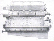
Current for auxiliary purposes is provided by four Diesel-engined generators, two on the port side and two to starboard. These are of 200 kw. apiece and have a speed of 225 r.p.m., current being supplied at 220 volts. The balance and generally good operation of the engines are commendable and contribute to the absence of vibration throughout the ship. Oversize compressors are fitted and accordingly no separate electrically driven auxiliary compressors are required to charge up the starting air containers.
Each engine has six cylinders with a diameter of 330 mm., corresponding to approximately 13", the piston stroke being relatively large, namely, 600 mm., which is equivalent to 23.5". Apart from this point the design corresponds to the usual Harland-B. and W. auxiliary four-stroke trunk-piston type of engine, but it may be added that in accordance with the latest practice the camshaft is driven by means of a chain. A feature not usually found on the smaller sizes of this class of motor is the electrically driven turning gear.
The emergency lighting sets, which are comparatively powerful installations, are in a special compartment on the boat deck. Each consists of a three- cylinder Harland-B.and W. trunk- piston four-stroke engine with a diameter of 200 mm., or about 10.25"., the piston stroke being rather less, i.e., 250 mm., corresponding to approximately 9 ins. ; the revolutions are 400 per minute. It may be observed that these engines are mounted on Mascolite seating's, and are complete with their own silencers and starting air bottles, a switchboard being arranged athwartships. Assuming a stoppage of the auxiliary generators below, the emergency sets are capable of running the brine pumps for the refrigerating plant and maintaining the temperature of the refrigerated holds at the correct degree. The dynamos are Laurence Scott machines, each having a capacity of 227 amperes, current being generated at 220 volts.
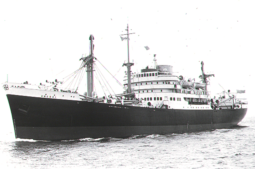
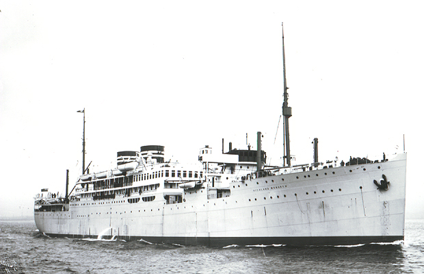
From the view of the vessel which appears on another page -it will be seen that a pair of short funnels gives her a distinctive appearance. One of these contains the silencers and salt water tanks, whereas the other forms a comparatively spacious compartment fitted with a skylight and housing a couple of Quiggin’s fresh-water filters, together with a fresh-water tank. On the trip round from Belfast the novel practice was adopted of illuminating the funnels with the powerful lights used when lowering the lifeboats at night; normally, however, the lights are for illuminating the unusually large deck space on which dancing may take place. [Motor ship November 1928] |
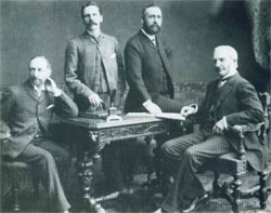 The PartnersHarland, Wolff, Pirrie and Wilson
 The HatsChairmen, MD's, CEO's
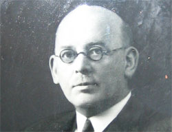
 Sir Frederick RebbeckChairman 1930-41 1944-62
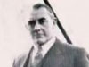
 Sir Charles PalmourChairman 1941-1944
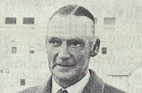
 John S BallieChairman 1962-1965
 Dr Dennis RebbeckChairman 1965-1966
 Sir John MallabarChairman 1966-1970
 Joe R EdwardsChairman 1970
 Alan WattActing Chairman 1970-1971
 Lord RochdaleChairman 1971- 1975
 Sir Brian MortonChairman 1975-1980
 Victor Alexander CookeChairman 1980-1981)
 Vivian WadsworthChairman 1981-1982
 Sir John ParkerChairman 1982-1992
 Islandmen(and Women)
 Save our ShipyardSupport and solidarity
 The War MemorialsWe Will Remember Them
 The Bible Class
 Nicknames
 The Yarns(and Tall Tales)
 The Shipyard IndentureJW Mullholland