"The Engineer" Jan 28 - 1898
A TRAVELLING GANTRY FOR SHIPBUILDLNG
If British engineering are at times justly reproached for their dogged adherence to old machines and old methods, British shipbuilding are, at any rate, entirely blameless in this respect. They may fairly claim to be the leaders of the world in the development of new systems of shipbuilding, and to be the most open-handed of all nations in the trial of elaborate and costly experiment, and in the construction of expensive tools and apparatus. Of all our great firms there is probably not one which watches more closely the modern development of machinery and the application of it to their own craft than Messrs. Harland and Wolff. At the same time the magnitude of the work they undertake makes it necessary that all their endeavour to maintain their position should be made on a large scale. A magnificent example is before us.
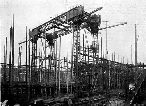
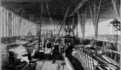
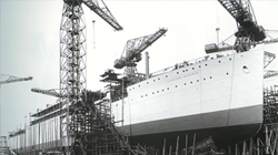
Fig. 1
- General view of the Gantry
The accompanying photographs show a large new hydraulic shipbuilding travelling gantry, recently supplied to them by Messrs. Fielding and Plait, Limited, to be used in the construction of the S.S. Oceanic, which they are now building for the White Star Line. This gantry is built throughout of steel, and the use of lattice bracing throughout, with the addition of rigidly-braced plate girder at the corners where the vertical and horizontal portions meet, has rendered it strong and rigid - see Fig. 1. At the four corners are fixed four travelling jib cranes for suspending portable riveting and punching machines, and for the handling of material. Each crane is capable of lifting a load of about 4 tons through a height of 80ft. at a rake of 40ft. All the motions —lifting, racking, and slewing are performed by hydraulic power. The cranes swing through an angle of 180 degrees, and can thus cover a space of about 80ft. on each side of the centre line of ship. The hydraulic cylinder and valves for operating them are fixed to the four legs of the gantry near the ground line. Steel wire ropes pass over guide pulleys for controlling the several motions.
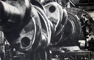
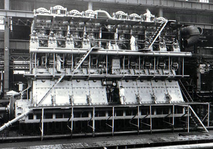
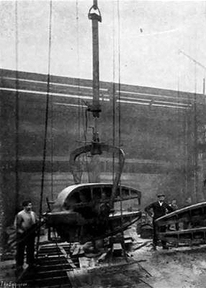
In addition to these four jib cranes there are three hydraulic travelling cranes working at the top of the gantry; two of these work at higher level than the third, as can be seen from the engraving, Fig. 1. This arrangement makes it possible to work the several machines closer together than could other wise be done. These cranes are intended mainly for carrying portable riveting machines, which are supported by hydraulic lifts suspended from the travelling carriages of the cranes by flat steel links. These are so arranged that they can easily be put in or taken out according to the height at which the machine are being worked in Fig. 2. The riveting machines shown are arranged for riveting up the double bottom of a ship, but as the construction of the ship advances links will be taken out, and the machines brought to bear upon the decks and other parts.
The motion of the travelling cranes is controlled from the level at which the riveting machines are worked by band-chains depending from sprocket wheels on the cranes, and notwithstanding the great height at which the cranes are above the machines no difficulty has been found in completely and easily controlling the various motions, indeed, the greater flexibility in the movement of the machines due to this great height is found to be a positive advantage. The gantry is propelled up and down upon double rails, placed on each side of the berth, by two hydraulic engines actuating work gear upon the travelling wheels.
In order to ensure that both sides of the gantry should always advance equally, the two sides are geared together by vertical and horizontal shafts carried up two of the legs and across one of the main top girders. The hydraulic engines are of the three-cylinder, single-acting type, with externally hemp-packed rams, all parts being easily accessible. The rails on which the gantry travel consist on each side of the berth of a pair of strong steel H-section bars, having riveted upon the upper surface flat steel bars. The two H sections are braced together by cross pieces, and are bedded upon continuous blocks of concrete carried upon piles. The total length of the rails is about 650ft., and the span of the gantry measures 100ft. from centre to centre of each pair of double rails. The clear height from rail level to the underside of the cross girders of the gantry is 95ft., and the clear space between the vertical legs is 95ft.
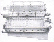
Hydraulic pressure and return piping is carried up each of the four legs and across the top of the gantry, suitable branch pieces and hydrants being provided where necessary for coupling to riveting machines, &c., in whatever positions they may be required. The pressure is taken from a hydraulic main running along the side of the berth, the connection Being made by large flexible armoured hose. The exhaust water is also returned to the pump station through suitable mains, so that the same water is used over and over again. Rivet heating furnaces have been placed by Messrs. Harland and Wolff at different levels on each side of the gantry, in such positions as will enable the machines to be easily supplied with rivets at any part of the ship. Staging and ladders are fitted to enable all parts of the gantry and machinery to be easily accessible for examination. In addition to the riveting machines shown in Fig. 3, others have also been supplied. These are of the direct-acting type, and have a gap of 7ft., and are capable of dealing effectively with 1 1/4in. rivets. The Fielding type machines seen in the engraving - have a gap of 6ft. and are of the same power. Messrs. Fieiding and Platt have also in construction for work in conjunction with the work of the gantry a power hydraulic portable punch, capable of punching 1 1/4in holes in plates 11/8in. thick. It will be used for punching the plates in the top strakes of the ship, the plates being fixed against others which have been previously drilled or punched, the portable machine using this as a template, thus ensuring exact fairing of holes.
Messrs. Harland and Wolff suggested the general lines on which this important work should be designed. To them also is due the idea of a very ingenious plan devised for getting over the practical difficulty of enabling the gantry to be worked upon the ground, the formation of which is not a uniform slope, and thus enabling a straight line of rails to be employed. To meet this difficulty they suggested making the profile of the line a circular are of very large radius.
 At the head of the slope the main angle of radius is much flatter than at the lower end of the berth, the result of which is that, when working at the upper end, the level of the travelling cranes at the top of the gantry is slightly inclined in one direction, whilst then the gantry is at the lower end of the berth they are inclined slightly in the other direction. This slight variation in angle, however, is of no practical importance, and does not interfere with the proper working of the cranes. The advantage of the curved profile of the rails is that no adjustment in the heights of wheel axles is required, whilst high embankments or a deep cutting are avoided.
The gantry has been found to be an entire success, and no accident to life or limb has been met with, which is highly satisfactory considering the magnitude of the job, and the difficulties met with when working at such a height, and often in heavy weather.
The entire contract for the supply of the Gantry and Machinery was in the hands of Messrs. Fielding and, Platt, Limited, of Gloucester, who are responsible for its efficiency. The building of the structure was sublet by them to Messrs. Arrols' Bridge and Roofing Company. Germiston Works, Glasgow, who have performed their portion of the work with their usual ability.
Left - Fig. 2 Riveting Machine on Lifts
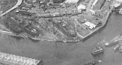
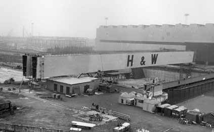
Queens Yard 1935 - 1968
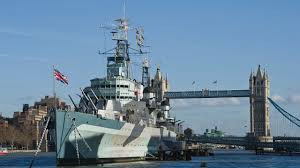
The last ship launched from the Queens Yard was HMS Charybdis, launched on the 28th February, 1968.

|
|
 The PartnersHarland, Wolff, Pirrie and Wilson
 The HatsChairmen, MD's, CEO's
 Sir Frederick RebbeckChairman 1930-41 1944-62
 Sir Charles PalmourChairman 1941-1944
 John S BallieChairman 1962-1965
 Dr Dennis RebbeckChairman 1965-1966
 Sir John MallabarChairman 1966-1970
 Joe R EdwardsChairman 1970
 Alan WattActing Chairman 1970-1971
 Lord RochdaleChairman 1971- 1975
 Sir Brian MortonChairman 1975-1980
 Victor Alexander CookeChairman 1980-1981)
 Vivian WadsworthChairman 1981-1982
 Sir John ParkerChairman 1982-1992
 Islandmen(and Women)
 Save our ShipyardSupport and solidarity
 The War MemorialsWe Will Remember Them
 The Bible Class
 Nicknames
 The Yarns(and Tall Tales)
 The Shipyard IndentureJW Mullholland